Audio
What was inside a radio I learnt already as a six year old boy, when my father gave me several discarded electron
tube radios, which I reduced to spare parts with a large hammer and pliers. Later, I began to understand what all
the shiny metal things were for, and wanted to build something myself.
During the years in gymnasiet (~senior high, ~upper secondary school), my big interest in building audio electronics
started. At that time I had started collecting various hi-fi pieces, and had my mind set on gathering more of them.
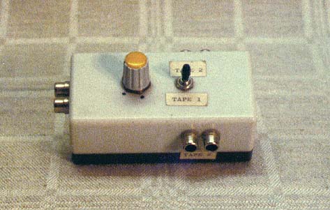
Switch for Two Tape Recorders
|
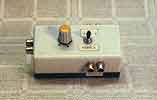 Let's start off with something simple, which
turned out to be very useful. I had several tape recorders and my amplifier had only one tape input. I very fast
built a little switch box which let me choose the appropriate recorder to play from. It also had a level regulator
so I could change the output level to match various amplifiers.
Let's start off with something simple, which
turned out to be very useful. I had several tape recorders and my amplifier had only one tape input. I very fast
built a little switch box which let me choose the appropriate recorder to play from. It also had a level regulator
so I could change the output level to match various amplifiers.
 In gymnasiet (~senior
high, ~upper secondary school) all technical students wanted to build hi-fi equipment. A friend and I designed
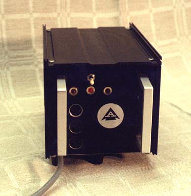
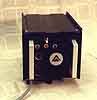
a very capable audio power amplifier and sold drawings and circuit boards to anyone who wanted to buy. I also built
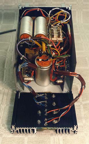
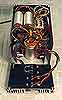
a compact version of this quite passable amplifier. The first picture is an external shot, and the next shows its
insides. Nearest you are the cooling fins with the power transistors (facing down). In the centre of the design
sits the large smoothing capacitor, with the rectifier bridge built in the air, using spaghetti technology. To
each side of it, are the amplifier boards, positioned so that they fit into grooves in the cooling fin. The output
capacitors lie on top, and to the right of them is the fuse board.
In gymnasiet (~senior
high, ~upper secondary school) all technical students wanted to build hi-fi equipment. A friend and I designed
a very capable audio power amplifier and sold drawings and circuit boards to anyone who wanted to buy. I also built
a compact version of this quite passable amplifier. The first picture is an external shot, and the next shows its
insides. Nearest you are the cooling fins with the power transistors (facing down). In the centre of the design
sits the large smoothing capacitor, with the rectifier bridge built in the air, using spaghetti technology. To
each side of it, are the amplifier boards, positioned so that they fit into grooves in the cooling fin. The output
capacitors lie on top, and to the right of them is the fuse board.
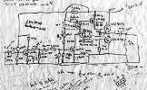
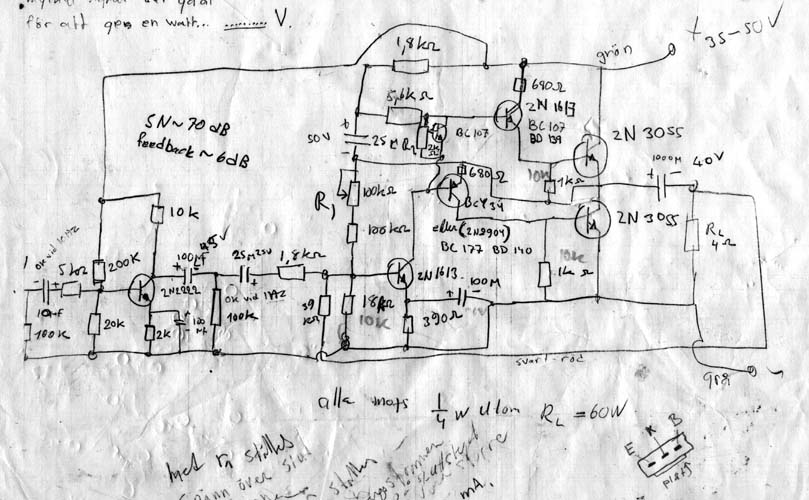
 Having two
2N3055's for power transistors, fed with 60 volts, it was possible to get 2x60 watts continuous power from it,
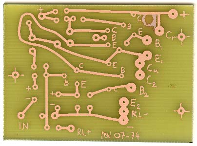
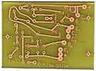
and some 2x100 watts in peaks. The first picture shows the schematic, pockmarked by experimental work. The next
picture shows the circuit board, displaying all traces of home manufacture.
Having two
2N3055's for power transistors, fed with 60 volts, it was possible to get 2x60 watts continuous power from it,
and some 2x100 watts in peaks. The first picture shows the schematic, pockmarked by experimental work. The next
picture shows the circuit board, displaying all traces of home manufacture.
We measured the frequency response and found that we could get full power at 40 kHz. The Golden Ears, the esoteric
hi-fi buffs frowned at the 2N3055 and BC 109 transistors, but the fact is that the difference from the Quad 303
power amplifier I bought later, hailed to the skies by critics for many years, was amazingly small.
I've always had a passion for loudspeakers. Already in compulsory school I made the first tries with primitive
loudspeaker boxes, large and small, but of course, sound-quality-wise catastrophes. While others were bending extra
long exhaust pipes for their mopeds in Handicraft, I was thinking about damping materials for my latest loudspeaker.
I made contact with the technician at the local disco and repaired his broken equipment, and had the opprotunity
to see how real loudspeakers were designed.
Working hard with the compass saw, I designed and built two pressure chamber loudspeakers and equipped them
with two SEAS 15" bass speakers each, one SEAS medium range and one treble dome tweeter. Fairly much a standard
design, but the best I had built so far. Towards the end of their lives, these rather gigantic loudspeakers were
cut in half and turned into four boxes, given away to brothers and friends in need.
After having grown out of the pressure chamber age, I went for the only right thing, an 80 centimetre horn speaker,
the so called 70/80-horn from a Swedish hi-fi magazine. The efficiency was superb. The loudspeaker cone hit the
bottom at 30 watts, but so what, your ears (and your stomach) hit the bottom much before that. Added to that were
some 40 cm medium range horns, big black glass fibre monsters, and some cast aluminium treble horns from Isophon.
Eventually the somewhat resonant medium range and treble horns were skipped in favour of factory made 1.2 metre
ribbon speakers from the Danish Dali company. Ribbon speakers have the smoothest reproduction of all the types
I have encountered. To me, the mixture of bass horn and ribbon, with an extra power amplifier to even out the differences
in efficiency, is an excellent combination.
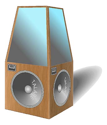
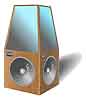 But I still miss the deepest bass notes. I do have a project for the
future, the pyramidal bass box, with an extra-long-throw (+/- 5 cm), home-brew loudspeaker element. It is still
in a dormant phase, although the magnet system, with parts from an old disk drive from a mainframe computer, is
largely finished (glass fibre voice coil, 10 cm diameter). My calculations has shown that a lower frequency limit
of some 3 Hz is not unreachable. The upper, shiny areas are mirrors. Why not make the thing nice-looking? The picture
is a CorelDRAW simulation.
But I still miss the deepest bass notes. I do have a project for the
future, the pyramidal bass box, with an extra-long-throw (+/- 5 cm), home-brew loudspeaker element. It is still
in a dormant phase, although the magnet system, with parts from an old disk drive from a mainframe computer, is
largely finished (glass fibre voice coil, 10 cm diameter). My calculations has shown that a lower frequency limit
of some 3 Hz is not unreachable. The upper, shiny areas are mirrors. Why not make the thing nice-looking? The picture
is a CorelDRAW simulation.
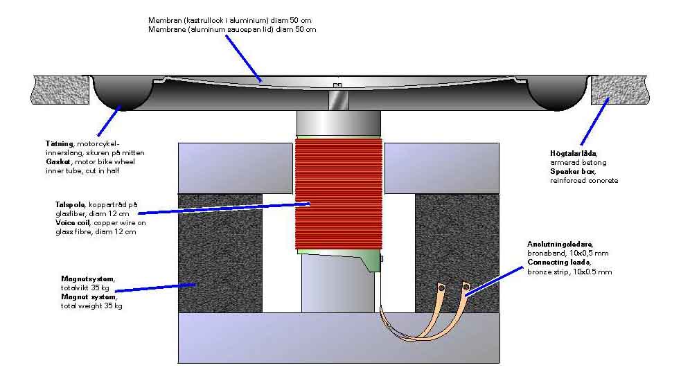
 Building the moving parts of the loudspeaker
element, I had come to the membrane and its suspension and tightening against the speaker box. The membrane should
be half a meter in diameter, light and strong. My ideal turned out to be a king size saucepan lid. I went to a
shop selling extravagant French kitchen supplies.
Building the moving parts of the loudspeaker
element, I had come to the membrane and its suspension and tightening against the speaker box. The membrane should
be half a meter in diameter, light and strong. My ideal turned out to be a king size saucepan lid. I went to a
shop selling extravagant French kitchen supplies.
- I would like a big, strong saucepan lid made out of aluminium.
- What saucepan do you have?
- I don't have any. I'm building a loudspeaker.
This comedy was repeated later when I went to buy some tightening, i.e. the flexible part that sits between
the membrane and the box. Preferably it should be made from rubber, be round as a ring, and fit outside the saucepan
lid. I went to a motorcycle shop and asked for a suitably sized inner tube.
- How do you do? I would like to buy an inner tube.
- What wheel do you have?
- I don't have a wheel. The tube must fit outside this saucepan lid. I'm building a loudspeaker.
- (in disbelief) Will Firestone be okay, then?
 Mail-order catalogues
have always been a source of inspiration, and when a binaural microphone popped up one year, my building fingers
started itching anew.
Mail-order catalogues
have always been a source of inspiration, and when a binaural microphone popped up one year, my building fingers
started itching anew.
Using ordinary multi-microphone stereo it is possible to control the stereo scenario any way you want with the
mixer, but the sound picture remains flat, stretched out between the speakers. With our natural hearing on the
other hand, we can hear sounds behind and in front of us, as well as above and below. Without this ability we wouldn't
last very long in everyday life.
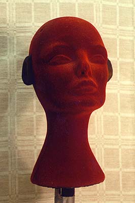
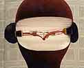
Using artificial head stereo, or binaural stereo, it is possible to mimic the human hearing and record a soundscape
like that of the human hearing. It is the shape of the head, attenuation of the treble frequencies by the hair,
the shape of the ears and the shoulders that gives the ears the possibility to register the minimal differences
in frequency response and time displacement that the brain interprets as spatial information.
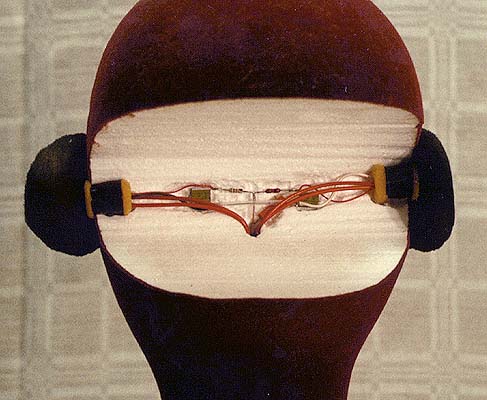
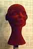
I got myself a mannequin head made of light plastic and mounted two microphones in its auditory meatus, quickly
excavated with a soldering iron. The ears are important, so I made ears out of foam rubber and enamelled them with
spray paint to give them the proper shape and consistency. The effect was overpowering. I also made an LP record
with binaural sound. Read more about it in the text about my technical career.
VU Meter with Oscilloscope
|
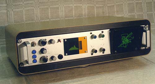
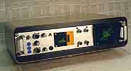 I had serious thoughts about beginning to record live music
on a regular basis, and I had discovered the limitations of the Revox VU meters. I needed something more snazzy,
something with a real time display. As usual, I aimed for something big, and built a VU meter containing an oscilloscope
and an elctroluminiscent bar graph display for the frequency spectrum. The absolute VU indicator. The picture shows
the outside of the box. Starting left we see the power switch and indicators, followed by input selectors and some
10 turn potentiometers for calibration. In the middle sits the spectrum analyser display, followed by positioning
knobs for the CRT and to the far right, the CRT itself.
I had serious thoughts about beginning to record live music
on a regular basis, and I had discovered the limitations of the Revox VU meters. I needed something more snazzy,
something with a real time display. As usual, I aimed for something big, and built a VU meter containing an oscilloscope
and an elctroluminiscent bar graph display for the frequency spectrum. The absolute VU indicator. The picture shows
the outside of the box. Starting left we see the power switch and indicators, followed by input selectors and some
10 turn potentiometers for calibration. In the middle sits the spectrum analyser display, followed by positioning
knobs for the CRT and to the far right, the CRT itself.
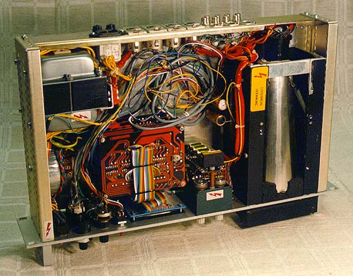
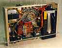 From the right we see the CRT contained in
double mu-metal screens, with shock absorbing felt inlays. Its front is mounted in a customized rubber foam block.
Additionally, it is caged in protective aluminium profiles. This set was designed for being knocked about. Going
left we see the high-voltage unit and the positioning potentiometers. In the middle we see the spectrum analyser.
The power supply is at the top left.
From the right we see the CRT contained in
double mu-metal screens, with shock absorbing felt inlays. Its front is mounted in a customized rubber foam block.
Additionally, it is caged in protective aluminium profiles. This set was designed for being knocked about. Going
left we see the high-voltage unit and the positioning potentiometers. In the middle we see the spectrum analyser.
The power supply is at the top left.
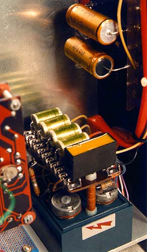
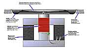
 A tasty close up of the high-voltage
unit. The potentiometers for the beam XY positioning are mounted in the green plastic box, and protrudes through
the front panel with plastic shafts. On top of the box is the voltage divider and smoothing capacitors giving deflection
voltage to the deflection plates. In the top right of the picture are the somewhat bigger, yellowish smoothing
capacitors in the voltage multiplier giving the CRT high voltage, and below these (hidden) are the diodes for the
same (actually mounted on a Formica board salvaged from and old marine radar).
A tasty close up of the high-voltage
unit. The potentiometers for the beam XY positioning are mounted in the green plastic box, and protrudes through
the front panel with plastic shafts. On top of the box is the voltage divider and smoothing capacitors giving deflection
voltage to the deflection plates. In the top right of the picture are the somewhat bigger, yellowish smoothing
capacitors in the voltage multiplier giving the CRT high voltage, and below these (hidden) are the diodes for the
same (actually mounted on a Formica board salvaged from and old marine radar).

 Let's start off with something simple, which
turned out to be very useful. I had several tape recorders and my amplifier had only one tape input. I very fast
built a little switch box which let me choose the appropriate recorder to play from. It also had a level regulator
so I could change the output level to match various amplifiers.
Let's start off with something simple, which
turned out to be very useful. I had several tape recorders and my amplifier had only one tape input. I very fast
built a little switch box which let me choose the appropriate recorder to play from. It also had a level regulator
so I could change the output level to match various amplifiers.