or, why I started with amateur radio, and then gave it up.
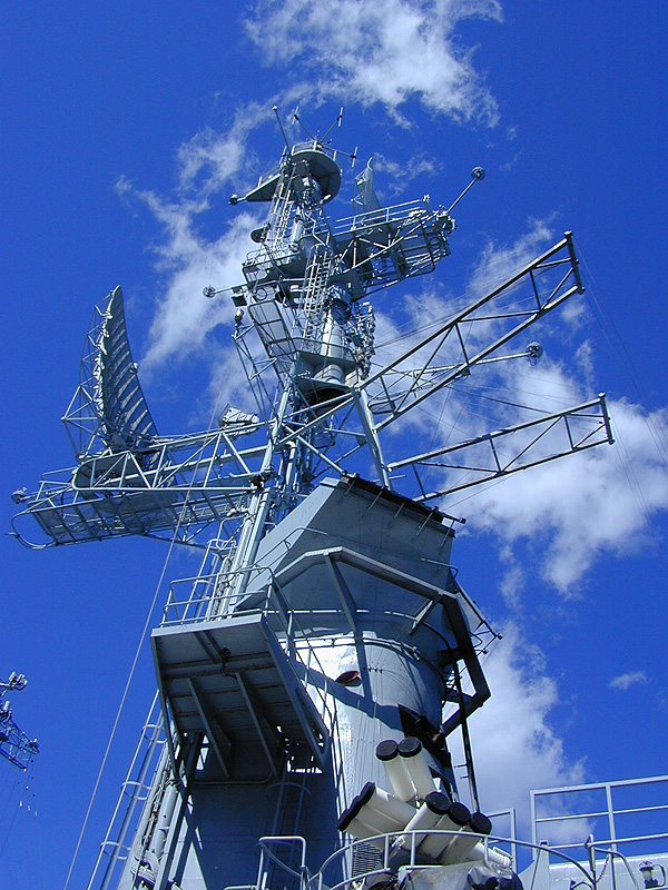
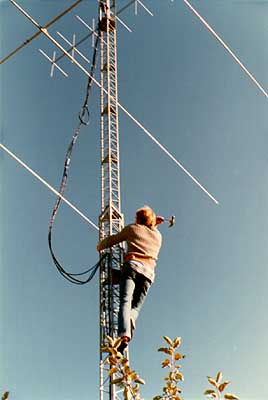
Only the military can sport such an exquisite antenna farm. Click the picture and count them!
The idea of amateur radio caught my imagination the moment I heard of it. Just imagine, to be able to sit in front of a transmitter and talk to people on the other side of the Earth. I reasoned that among radio amateurs there must be some good technicians, had my licence in a jiffy, became SM0FIX, got myself a transmitter and started searching for people to talk with about advanced electronics.
What a mistake! The amateurs were ordinary people, and most of them had bought their sets ready made and used them like intercoms. The pioneering spirit so hailed in the amateur radio magazines was long gone. My interest in classic amateur radio waned, as I started to realize that it was possible to carry on a one-hour more or less meaningless radio conversation on the very simplest of matters, such as the length of a dipole or the design of Yagi antennas. That's the stuff you read in The Radio Amateur's Handbook before you do anything else. I soon learnt how to design antennas without the aid of handbooks.
I can make an antenna for 144 MHz (2 metres wavelength) in ten seconds, using only a knife. OK then, 20 seconds. If you should ever find yourself in an emergency situation (frozen up in Antarctica, lost in Africa) and need an antenna fast, just follow these simple steps:
Your antenna is finished.
A true technician will now argue that I haven't compensated for the lower speed of light in the RG58 and that the braid gets slightly longer than the inner conductor when you pull it. Never mind. It works well anyway.
Also, this antenna has the advantage that once you have finished working, you just pull it down and roll it up together with the coaxial cable.
 Having used an ordinary GP antenna for some time with
my 2 metre equipment, I realized a directional antenna would be infinitely better. Instead of being moderate and
making it simple, I scanned the handbooks and built myself a 7 element Yagi. It became some 2 metres long. It is
the uppermost antenna in the picture.
Having used an ordinary GP antenna for some time with
my 2 metre equipment, I realized a directional antenna would be infinitely better. Instead of being moderate and
making it simple, I scanned the handbooks and built myself a 7 element Yagi. It became some 2 metres long. It is
the uppermost antenna in the picture.
As there are both horizontally and vertically polarized radio stations, I also fitted another set of antenna radials at 90 degrees angle to the first, and got two antennas in one: A cross Yagi.
I would also get double the gain if I built another antenna of the same kind and mounted it one wavelength away. Very well. Also, the backward lobes (the non-useful radiation emitted from the back of the antenna) would not look so nice with a standard, single reflector element. I cut another ten reflector elements and made a full reflector plane in the rear, and got myself a superb forward/backward ratio.
To top it all off we had recently learnt how to calculate impedances using Schmitt Charts at school. I now used this to impedance-match the antennas, connecting them to the same feeder line. So there is something useful with school, anyway!
That antenna turned out so well I could regularly open the Örebro repeater (slave transmitter for radio amateurs) using only my 10 Watts of output power from Södertälje (140 km). When the conditions were good, I could even reach Norway.
I had even better conditions after one storm, when the antennas were knocked 45 degrees up in the air. I cold hear signals that were shifting very strangely in frequency, as if the transmitter was drifting. It was OSCAR: Orbiting Satellite Carrying Amateur Radio. That was the best fun I had with that antenna.
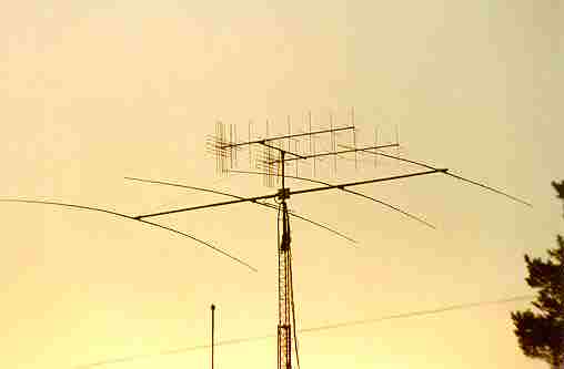
The magnificent Yagi antenna in the picture above, I built together with a friend, to achieve the best possible reception in the short-wave 20 metre band. Of course we had cast longing looks at the log-periodic Yagi at the roof of the Foreign Office in Stockholm, but we would have to do as best we could with our 4 elements. It is the lowermost antenna in the picture above.
The antenna turned out 10x11 metres, that is 110 m2, slightly larger than the house. We wanted Full Size and no shortened compromises with shortening coils. The problem was not building and tuning it, the problem was getting it on top of the radio tower. Well, with the aid of a few friends we finally made it.
What an antenna! We were ravished. We had telephone quality all the way to Australia any time we wanted. Our 2 kilowatts of output power made the picture on all nearby TV sets fall over, which, in the end limited the usefulness of the antenna.
Together with a friend I happened to find an APX-6, an American surplus IFF (Identification Friend or Foe) radar identification transmitter. It was a micro wave unit used at about 1,5 GHz in fighter aircraft, for listening to American radar and sending back an identification together with the radar echo, telling the radar operator it was a friend and not a foe on the screen.
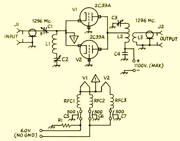 It was a small (40x40x40 cm) black box, stuffed full of electron
tubes and cabling. We removed most of it, but kept the microwave stuff and the intermediate frequency strip. We
also built a new audio part, using electron tubes, to be able to use the set as a communications transceiver. The
schematics shows a power amplifier for 1296 MHz, at which I also tried my hands.
It was a small (40x40x40 cm) black box, stuffed full of electron
tubes and cabling. We removed most of it, but kept the microwave stuff and the intermediate frequency strip. We
also built a new audio part, using electron tubes, to be able to use the set as a communications transceiver. The
schematics shows a power amplifier for 1296 MHz, at which I also tried my hands.
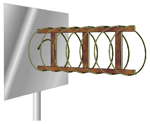 It was quite a nice project in itself, that gave insights into the art of
tuning microwave cavities. An antenna was also needed. With some help from the The ARRL Antenna Book I built
a helical antenna for 1296 MHz that worked well. Not only could we communicate on the 20 centimetre band, but if
the antenna was directed upwards we heard the strangest of things: DME signals from aeroplanes. The Distance Measuring
Equipment is a method of navigation using series of short microwave pulses transmitted from aircraft to ground
stations. The ground station returns the signal, and by using triangulation, the computer in the aircraft can calculate
its position. Anyway, it sounds bzzzp-bzzzp-bzzzp!
It was quite a nice project in itself, that gave insights into the art of
tuning microwave cavities. An antenna was also needed. With some help from the The ARRL Antenna Book I built
a helical antenna for 1296 MHz that worked well. Not only could we communicate on the 20 centimetre band, but if
the antenna was directed upwards we heard the strangest of things: DME signals from aeroplanes. The Distance Measuring
Equipment is a method of navigation using series of short microwave pulses transmitted from aircraft to ground
stations. The ground station returns the signal, and by using triangulation, the computer in the aircraft can calculate
its position. Anyway, it sounds bzzzp-bzzzp-bzzzp!
I haven't retained the transceiver. I gave it to an amateur radio astronomer who uses it for listening to supernovae.
 I quickly realised I needed a high antenna tower to
become a real radio amateur. Additionally, it needed an antenna rotator in the top, to turn the antennas into
any direction. I sat, dreaming over some mail-order catalogue and found that a factory-made tower would be far
too expensive.
I quickly realised I needed a high antenna tower to
become a real radio amateur. Additionally, it needed an antenna rotator in the top, to turn the antennas into
any direction. I sat, dreaming over some mail-order catalogue and found that a factory-made tower would be far
too expensive.
I read everything about girders in theory and practice and designed my own two section 18 metre tower. It could be cranked down to half the height with a winch, by having the upper section sliding inside the lower one.
My poor, pushed around father helped me with the welding and after one week we had a nice, galvanized tower that was extremely strong.
The tower was mounted on an a large hinge on a lump of concrete we put in the ground. That lump was so well made it was impossible to remove it later when the tower was sold. Today it serves as a flower pedestal.
The hinge made the tower removable, and it could be lowered in some suitable direction in the garden, for servicing.
The tower became very strong. There were no problems having one person sitting at the top, swaying from side to side. It stood through one of the worst autumn storms Sweden has had for 50 years without a hitch, a storm that tore the roofs of neighbouring houses. The output gearwheel in the rotator broke with a crunching noise in the middle of the night and the antennas started spinning freely, but after I secured the antennas everything was fine.
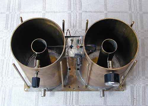 Always hunting for lower
noise levels and better reception, I decided to build an extra RF amplifier for my 2 metre receiver. I also decided
to go for something exclusive, so I built one with FET transistors having ultra low noise, and cavity tuning on
top of this, to increase selectivity. Cavities are resonant circuits made in the form of large metal jars. That
yields better and more stable operation than making the same resonant circuits out of coils and capacitors.
Always hunting for lower
noise levels and better reception, I decided to build an extra RF amplifier for my 2 metre receiver. I also decided
to go for something exclusive, so I built one with FET transistors having ultra low noise, and cavity tuning on
top of this, to increase selectivity. Cavities are resonant circuits made in the form of large metal jars. That
yields better and more stable operation than making the same resonant circuits out of coils and capacitors.
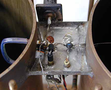 The design is quite simple. I took two
brass tubes and turned them into the right diameter, placed them on a base plate and gave them top lids. Everything
was held together with vertical bolts. One jar was the input circuit and the other one the output circuit. Between
them was a short bridge, on which I built the amplifier, using only very few components. Tuning was accomplished
with a variable capacitor in each jar.
The design is quite simple. I took two
brass tubes and turned them into the right diameter, placed them on a base plate and gave them top lids. Everything
was held together with vertical bolts. One jar was the input circuit and the other one the output circuit. Between
them was a short bridge, on which I built the amplifier, using only very few components. Tuning was accomplished
with a variable capacitor in each jar.
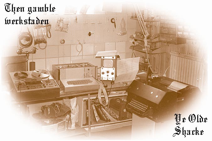 The teletype is an old kind of all-mechanical telex machine.
Of course I didn't build it myself. Creed built it, a long time ago. I bought it as surplus from another radio
amateur and used it for printing news bulletins from news agencies transmitting on the short-waves. It was a terrible
monster, making an incredible amount of noise. I finally silenced it by nailing heavy carpet inside its wooden
cover. The picture shows my workshop at the end of the 70's. The teletype stands majestically to the far right.
To the left is an oscilloscope we used for monitor, next our home-brew keyboard in front of the home-brew 8-bit
computer, and to the far left the tape recorder I used for recording signals from the short-waves.
The teletype is an old kind of all-mechanical telex machine.
Of course I didn't build it myself. Creed built it, a long time ago. I bought it as surplus from another radio
amateur and used it for printing news bulletins from news agencies transmitting on the short-waves. It was a terrible
monster, making an incredible amount of noise. I finally silenced it by nailing heavy carpet inside its wooden
cover. The picture shows my workshop at the end of the 70's. The teletype stands majestically to the far right.
To the left is an oscilloscope we used for monitor, next our home-brew keyboard in front of the home-brew 8-bit
computer, and to the far left the tape recorder I used for recording signals from the short-waves.
The standard speed for radio amateurs happened to be 45.45 bps, whereas this teletype used 50 bps, as it was a telex machine. Accompanying the machine was a custom filed tuning fork, tuned to 125 Hz with a stroboscopic add-on. Using this and a stroboscopic paper strip taped to the speed variator of the motor, I was able to tune the motor speed to the required 45.45 bps.
The problems started when I began to use the teletype. The motor emitted so much electrical noise on the short-waves that all news stations weaker the S9+20 (really strong) were drowned, which were most of them, save for the communist countries' propaganda transmitters. The Creed motor, a sparking series motor with exposed brushes, was my first interference elimination project. I had to make a motor, giving off millimetre-long sparks, so quiet it wolud be possible to receive short-wave stations at microvolt levels on a receiver sitting only half a meter away. The motor itself was all metal, and didn't emit any interference. All interference came from the openings for the brushes. A mixture of radiated and conducted interference, in other words. All paint was removed around the one end of the motor with open holes and a screening container was manufactured of silver, fitting nicely over the motor's end. The leads were brought in via two feedthrough capacitors, soldered to the container. The result was an almost silent motor, making no more noise than S2 on the short-waves (barely audible), and the road was now open to news reception from all around the world, from Egypt among other countries. You can read more about interference suppression here.
 I needed some sort of decoder (what we
today would call a modem) that could convert the signals from the receiver into pulses powerful enough to drive
the magnet inside the teletype. The EL 34 was a big and strong electron tube (and it came free from any old radio),
that was not exactly able to take the magnet current, but with some persuading and with glowing anodes it worked
fine. The schematic shows this very first RTTY decoder. It was rather "coarse" and worked if the receiver
was tuned slightly off the station. It didn't really do any frequency shift detection. It wasn't very good.
I needed some sort of decoder (what we
today would call a modem) that could convert the signals from the receiver into pulses powerful enough to drive
the magnet inside the teletype. The EL 34 was a big and strong electron tube (and it came free from any old radio),
that was not exactly able to take the magnet current, but with some persuading and with glowing anodes it worked
fine. The schematic shows this very first RTTY decoder. It was rather "coarse" and worked if the receiver
was tuned slightly off the station. It didn't really do any frequency shift detection. It wasn't very good.
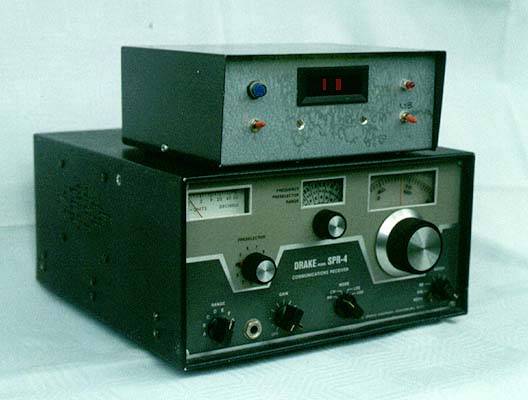
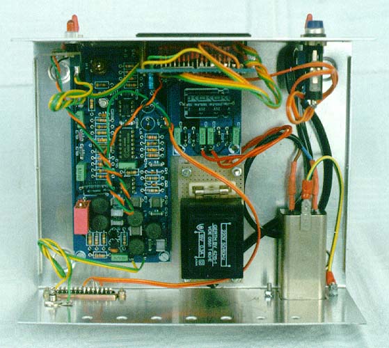
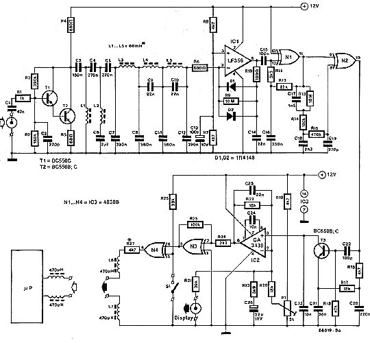 Later, the Elektor Magazine published a kit for a solid state decoder, also having a
very flashy display. I built it and gave it a heavy duty output stage so it could drive my Creed teletype. The
first picture shows the decoder on top of my Drake SPR-4 receiver. The next picture shows the innards of the decoder,
and the last picture shows the schematic. This decoder was a true frequency shift detector, having a narrow bandwidth.
Using the display, it was easy to tune the receiver correctly, and the reception of news bulletins from the short-waves
was vastly improved.
Later, the Elektor Magazine published a kit for a solid state decoder, also having a
very flashy display. I built it and gave it a heavy duty output stage so it could drive my Creed teletype. The
first picture shows the decoder on top of my Drake SPR-4 receiver. The next picture shows the innards of the decoder,
and the last picture shows the schematic. This decoder was a true frequency shift detector, having a narrow bandwidth.
Using the display, it was easy to tune the receiver correctly, and the reception of news bulletins from the short-waves
was vastly improved.
My hearing also improved during the experimental work, and after some time I could tune the receiver without the help of the display. For a while I was even able to hear what type of transmission was received, transmission speed etc., by just listening to the data stream. The brain is a strange device!
The Drake SPR-4 is a wonderful receiver, one of the best ones ever made. Today there may be receivers more stable in frequency, and the banks of crystals are forever gone, but when it came to selectivity the SPR-4 was superior to anything on the market in its time. One could be pretty sure that if it wasn't possible to hear a certain station with that receiver, it just wasn't there.
 But all this faded in front of what we
got to hear next, from the Linköping Technical Institute (LiTH) in the 80's: wireless computer networks. This
was completely new at the time, at least to us radio amateurs. The network was operated on the 432 MHz amateur
band and everyone could buy a kit and join in. LiTH hosted several symposia, and there was a sister club formed
in Stockholm. We built and built, and programmed the client stations in Forth, which was new and exciting then.
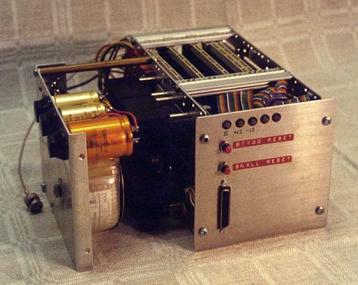
Above all, Forth was fast and compact, and saved memory. The picture shows my version of the Softnet node, having
the power supply to the left, and a short circuit board bay for the computer boards to the right. On the front
panel are a few lamps showing voltages, traffic etc., and below them, reset buttons. At the very bottom is the
serial port to the client terminal. The Softnet node was a complete, autonomous unit. It was able to build a network
in the air, find its neighbouring nodes and forward data packets from other nodes, all on its own.
But all this faded in front of what we
got to hear next, from the Linköping Technical Institute (LiTH) in the 80's: wireless computer networks. This
was completely new at the time, at least to us radio amateurs. The network was operated on the 432 MHz amateur
band and everyone could buy a kit and join in. LiTH hosted several symposia, and there was a sister club formed
in Stockholm. We built and built, and programmed the client stations in Forth, which was new and exciting then.
Above all, Forth was fast and compact, and saved memory. The picture shows my version of the Softnet node, having
the power supply to the left, and a short circuit board bay for the computer boards to the right. On the front
panel are a few lamps showing voltages, traffic etc., and below them, reset buttons. At the very bottom is the
serial port to the client terminal. The Softnet node was a complete, autonomous unit. It was able to build a network
in the air, find its neighbouring nodes and forward data packets from other nodes, all on its own.
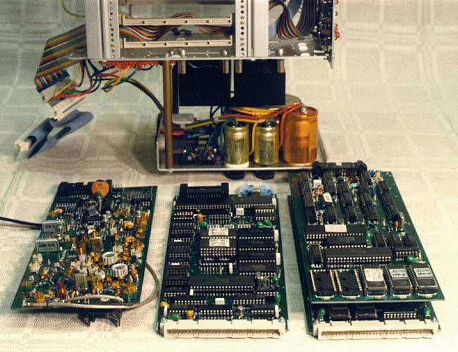 Actually the node contains two CPU's,
one for communication with the radio network and one for communication with the user terminal. The picture shows
the Softnet node pulled apart. At the rear stands the card rack with the power supply, with the circuit boards
in front: (from left) the transmitter, the link computer (controlling the radio) and the node computer (interfacing
the user).
Actually the node contains two CPU's,
one for communication with the radio network and one for communication with the user terminal. The picture shows
the Softnet node pulled apart. At the rear stands the card rack with the power supply, with the circuit boards
in front: (from left) the transmitter, the link computer (controlling the radio) and the node computer (interfacing
the user).
The wireless network was of the CSMA/CD type, i.e. exactly the same as the Ethernet in all cable networks today. The access to the radio medium was controlled by the link computer, handling all the low level communication with other nodes, error checking etc. The logical layout of the network, the method of building a two dimensional cellular network, forwarding of packets to other nodes, routing etc., was controlled by the node computer. The node computer was largely freely programmable, as the main idea with this project was to conduct research about routing in this type of radio networks.
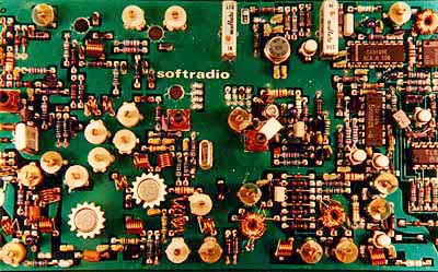 The radio board itself is a real goody.
To the left are drivers and output stages for 432 MHz and to the right are the digital input and output stages,
and the modulator.
The radio board itself is a real goody.
To the left are drivers and output stages for 432 MHz and to the right are the digital input and output stages,
and the modulator.
 Here are the schematics of the radio
board. It is rather advanced. At the left you see the receiver, the demodulator and modulator and to the right
is the transmitter part, with oscillator, multiplier stages and power output stage. The transmitter had to fulfil
some rather advanced specifications. On one hand it should be very stable in frequency, i.e. crystal controlled,
at the same time it should be able to swing some 100 kHz. Two normally unmatchable demands, being matched very
elegantly by the Linköping designers in this design. You can read more about digital radio here.
Here are the schematics of the radio
board. It is rather advanced. At the left you see the receiver, the demodulator and modulator and to the right
is the transmitter part, with oscillator, multiplier stages and power output stage. The transmitter had to fulfil
some rather advanced specifications. On one hand it should be very stable in frequency, i.e. crystal controlled,
at the same time it should be able to swing some 100 kHz. Two normally unmatchable demands, being matched very
elegantly by the Linköping designers in this design. You can read more about digital radio here.
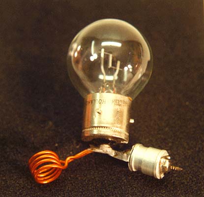 Sometimes, refinement will have to stand back to brute
force. Radio transmitters have to be tuned until they work properly. Something you often work with is getting the
output power up as much as possible. I soldered together a little device for output power testing: a 12 Volt 75
Watts incandescent lamp, tuned with a resonant circuit. The coil, at left, was put straight into the output coil
of the transmitter and the lamp was tuned with the capacitor, at right, until it lit up as much as possible. After
that you could tune the transmitter for maximum power, by just looking at the lamp. Very simple, and it worked
without batteries or electronics.
Sometimes, refinement will have to stand back to brute
force. Radio transmitters have to be tuned until they work properly. Something you often work with is getting the
output power up as much as possible. I soldered together a little device for output power testing: a 12 Volt 75
Watts incandescent lamp, tuned with a resonant circuit. The coil, at left, was put straight into the output coil
of the transmitter and the lamp was tuned with the capacitor, at right, until it lit up as much as possible. After
that you could tune the transmitter for maximum power, by just looking at the lamp. Very simple, and it worked
without batteries or electronics.