Miscellaneous
A lot of stuff I've built won't fit under any other category than this. Mostly, it's useful little testing
instruments, but also my own prototype breadboards.
My first High-Voltage Power Supply
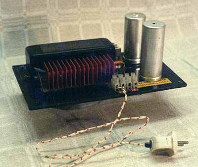
 This lethal thing should make any electricity safety
inspector gasp for his breath. It is just a simple 300 VDC power supply I built for development work with electron
tubes. It's a simple design. A rectifier salvaged from a TV set (the red one with fins) is mounted on a black acrylic
plate, together with a coil from a fluorescent tube assembly and two electrolytic capacitors from the same TV set
(the upright standing metal cans). A fuse is mounted in one corner. It's 220 VAC straight in. The device has no
feet, and had to be put on something insulating, or I would get very nasty sparks from the underside. Terrible.
But if you just keep your hands off, there is no danger. I can't remember ever getting any shocks from any of my
designs.
This lethal thing should make any electricity safety
inspector gasp for his breath. It is just a simple 300 VDC power supply I built for development work with electron
tubes. It's a simple design. A rectifier salvaged from a TV set (the red one with fins) is mounted on a black acrylic
plate, together with a coil from a fluorescent tube assembly and two electrolytic capacitors from the same TV set
(the upright standing metal cans). A fuse is mounted in one corner. It's 220 VAC straight in. The device has no
feet, and had to be put on something insulating, or I would get very nasty sparks from the underside. Terrible.
But if you just keep your hands off, there is no danger. I can't remember ever getting any shocks from any of my
designs.
Conductivity Tester
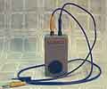 In all electric design work you sometimes need to know
if you have a connection or not. Of course you can drag the AVO-meter around everywhere, but this little conduction
tester, consisting solely of one Sonalert (beeper) and a battery is much tougher and doesn't have to be in view
all the time. If it beeps you have a connection. The device turned out to be invaluable in car repair.
In all electric design work you sometimes need to know
if you have a connection or not. Of course you can drag the AVO-meter around everywhere, but this little conduction
tester, consisting solely of one Sonalert (beeper) and a battery is much tougher and doesn't have to be in view
all the time. If it beeps you have a connection. The device turned out to be invaluable in car repair.
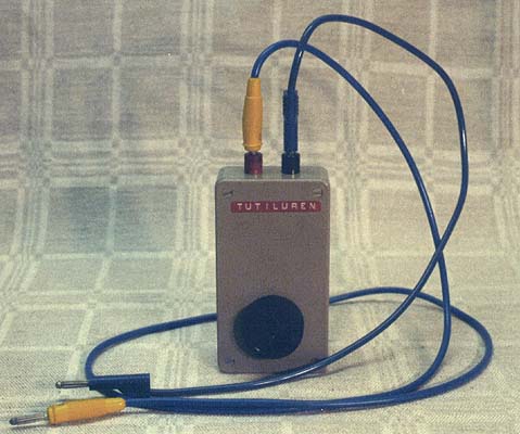
Stat-O-Meter: Static Electricity Meter
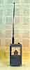
 I was dealing with
static electricity at work, or rather, tried to get rid of it. The problem was knowing how much static electricity
we were dealing with, and where it was generated. I needed some sort of measuring instrument. Meters could be bought,
but they were expensive and difficult to use (over-qualified). I built one myself, instead. The design was very
simple: the input of a FET OP-amp needing only a few nanoamperes is connected more or less straight to the antenna,
and so the amplifier is measuring the leak currents flowing in the air.
I was dealing with
static electricity at work, or rather, tried to get rid of it. The problem was knowing how much static electricity
we were dealing with, and where it was generated. I needed some sort of measuring instrument. Meters could be bought,
but they were expensive and difficult to use (over-qualified). I built one myself, instead. The design was very
simple: the input of a FET OP-amp needing only a few nanoamperes is connected more or less straight to the antenna,
and so the amplifier is measuring the leak currents flowing in the air.
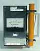
Using my Stat-O-Meter it was easy to trace static electricity, to check if a carpet created static charges,
and the like. Furthermore it could measure electrical changes in the atmosphere, measuring the weak currents flowing
through the air towards the clouds. These currents change when a thunderstorm is approaching. The meter has a recorder
output, making it possible to connect an X-t strip chart recorder and make long time measurements.
Infrared Photography
At work we were doing reading and detection of counterfeit bills by reading their image with a very special
camera and comparing with the properties of real bills. The problem was that banknotes sometimes were so dirty,
worn and torn that the camera had problems catching the picture properly. I found this so interesting that I started
to study infrared technology to see if it was possible to use other wavelengths than the visible. Kodak has a terrific
textbook on the subject, and armed with this I got myself a few filters, filter holders, film, lights and other
equipment, and started photographing dollar bills.
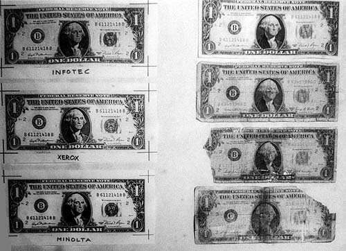
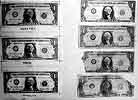 Sure enough, using short wave IR, with Kodak Wratten filter no. 87,
the dirt disappeared and the picture came through nice and clear. This picture is shot with f16. The bills to the
right are real (with real degradation) and the ones to the left are xerographic copies from different copy machine
manufacturers. I had to modify my camera. A camera lens does not refract IR in the same way as it does visible
light, so I had to calculate a new distance scale and draw it on the focusing ring. Of course I couldn't see through
the viewfinder, as infrared filters are completely opaque (black) in visible light.
Sure enough, using short wave IR, with Kodak Wratten filter no. 87,
the dirt disappeared and the picture came through nice and clear. This picture is shot with f16. The bills to the
right are real (with real degradation) and the ones to the left are xerographic copies from different copy machine
manufacturers. I had to modify my camera. A camera lens does not refract IR in the same way as it does visible
light, so I had to calculate a new distance scale and draw it on the focusing ring. Of course I couldn't see through
the viewfinder, as infrared filters are completely opaque (black) in visible light.
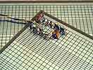
 And what's this? Sailboat racing in the middle of the
winter? A negative image? No, it happens to be in June. It is the sail race All-around Lidingö (north of
Stockholm) photographed in infrared light. This is evident from the strongly reflecting trees in the background,
and the nearly black water. The boats' sails also reflect strongly. The gas tank in the background is painted to
eat all incoming IR.
And what's this? Sailboat racing in the middle of the
winter? A negative image? No, it happens to be in June. It is the sail race All-around Lidingö (north of
Stockholm) photographed in infrared light. This is evident from the strongly reflecting trees in the background,
and the nearly black water. The boats' sails also reflect strongly. The gas tank in the background is painted to
eat all incoming IR.
IR Telescope
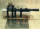
 I was involved
in the House Owner's Society and their work to make house-owning more economical. One big problem is heat leakage
from houses, mostly to find it and to measure how much heat is disappearing. I had seen the heat cameras from AGA
(a Swedish pioneering company in the IR camera business) and also seen the price tag. Just renting one was so expensive
you didn't do it unless there were severe suspicions about some fault. I decided to try to build a heat seeking
telescope, with telescopic sight and temperature indication in the form of a tone, so that you could sweep over
the wall of a house and listen to the leaks. A fantastic design that was unfortunately never finished.
I was involved
in the House Owner's Society and their work to make house-owning more economical. One big problem is heat leakage
from houses, mostly to find it and to measure how much heat is disappearing. I had seen the heat cameras from AGA
(a Swedish pioneering company in the IR camera business) and also seen the price tag. Just renting one was so expensive
you didn't do it unless there were severe suspicions about some fault. I decided to try to build a heat seeking
telescope, with telescopic sight and temperature indication in the form of a tone, so that you could sweep over
the wall of a house and listen to the leaks. A fantastic design that was unfortunately never finished.
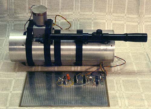
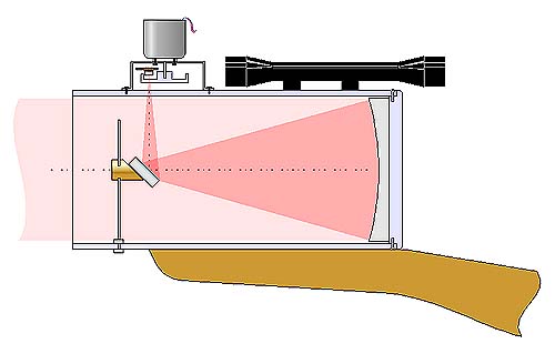
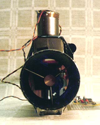
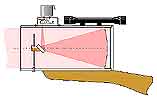
 The telescope consists of an aluminium tube with a
parabolic IR mirror in one end (which I actually managed to get from the camera department at AGA. Just think of
the things you can get hold of, if you talk to the right people) and a small secondary mirror at 45 degrees angle
in the middle of the telescope, directing the picture towards a sensor sitting in focus, right outside the telescope
tube. The picture shows what it looks like when looking straight into the telescope. You do see the camera?
The telescope consists of an aluminium tube with a
parabolic IR mirror in one end (which I actually managed to get from the camera department at AGA. Just think of
the things you can get hold of, if you talk to the right people) and a small secondary mirror at 45 degrees angle
in the middle of the telescope, directing the picture towards a sensor sitting in focus, right outside the telescope
tube. The picture shows what it looks like when looking straight into the telescope. You do see the camera?
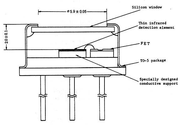
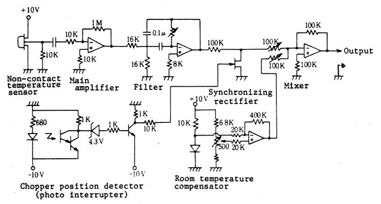
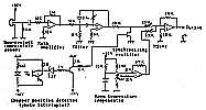 The sensor was
a derivating kind, having a silicon window. The semiconductor inside needed to see a reference temperature and
the true object temperature switched at about 10 Hz. I solved that by putting a rotating shutter, a chopper in
front of the sensor. The output from the sensor looked like a square wave, having an amplitude equal to the difference
in temperature between the chopper and the object. Hopefully, the chopper would keep a stable temperature throughout
the measurement period...
The sensor was
a derivating kind, having a silicon window. The semiconductor inside needed to see a reference temperature and
the true object temperature switched at about 10 Hz. I solved that by putting a rotating shutter, a chopper in
front of the sensor. The output from the sensor looked like a square wave, having an amplitude equal to the difference
in temperature between the chopper and the object. Hopefully, the chopper would keep a stable temperature throughout
the measurement period...
I got as far as mounting everything, and I managed to detect a soldering iron in the telescope's field of view.
Of course, the operator was not supposed to look through the telescope. It was only for the infrared radiation.
Instead I put a telescopic sight on the outside, one that I bought very cheap from a mail-order company. For the
operator's comfort under prolonged use, I mounted everything on a rifle butt, one that I got extremely cheap at
a gunshop. It looked like some futuristic raygun.
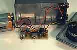
Geiger Counter
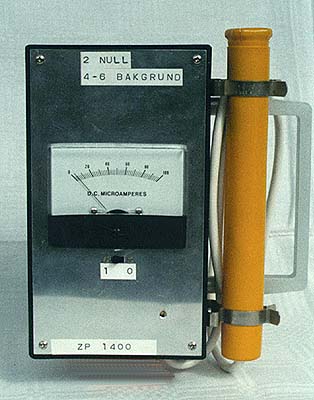
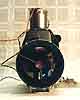
 The year was 1986. Suddenly some underpaid nuclear power plant workers
had finished playing in Chernobyl (actually meaning black existence, a fitting name) in Ukraine, and in one second
they had changed everybody's lives. The people at the Forsmark nuclear power plant in Sweden raised the alarm,
and suddenly having your own radiation counter was very popular. Buying one was unthinkable, as it cost several
thousands of kronor. I found some schematics and built one, but ran almost immediately into problems getting the
sensor, the Geiger-Müller tube. It turned out that everyone else had thought just like me, and there were
no GM tubes available in the whole country. After a lot of nagging I managed to get one from ELFA (a large mail-order
electronics dealer) and I could finish the counter. The GM tube is inside the yellow tube to the right. It was
such a disappointment! The counter worked, but there was nothing (enough) radioactive in my neighbourhood. Nothing
at all.
The year was 1986. Suddenly some underpaid nuclear power plant workers
had finished playing in Chernobyl (actually meaning black existence, a fitting name) in Ukraine, and in one second
they had changed everybody's lives. The people at the Forsmark nuclear power plant in Sweden raised the alarm,
and suddenly having your own radiation counter was very popular. Buying one was unthinkable, as it cost several
thousands of kronor. I found some schematics and built one, but ran almost immediately into problems getting the
sensor, the Geiger-Müller tube. It turned out that everyone else had thought just like me, and there were
no GM tubes available in the whole country. After a lot of nagging I managed to get one from ELFA (a large mail-order
electronics dealer) and I could finish the counter. The GM tube is inside the yellow tube to the right. It was
such a disappointment! The counter worked, but there was nothing (enough) radioactive in my neighbourhood. Nothing
at all.
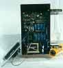
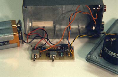
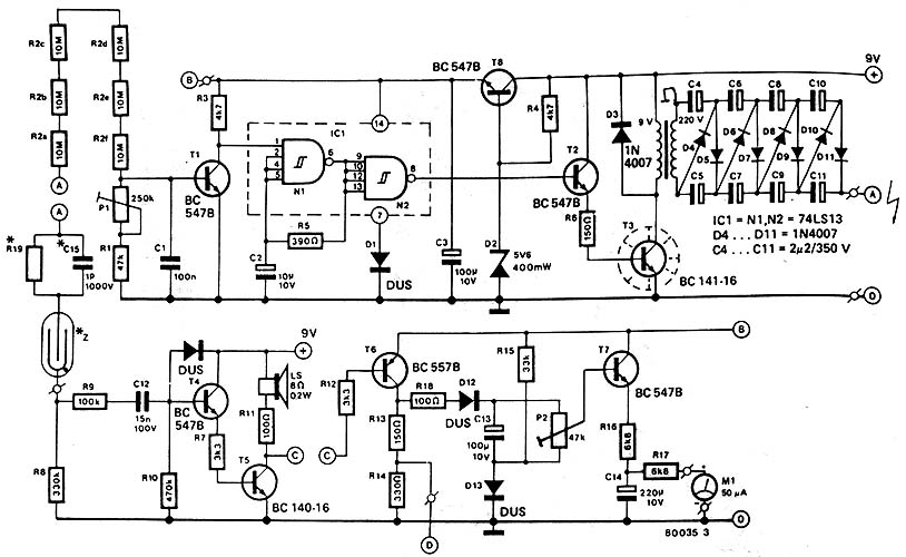
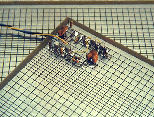
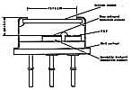
 The circuit board
is in the middle of the box. The blue electrolytic capacitors at the bottom are part of the voltage doubler, giving
800-900 volts to the GM tube. The tube itself is lying down to the right, with its hat off. The round, black thing
is the thin detector window. This window is so thin, both beta and alpha particles can penetrate it and ionise
the gas inside the tube. Gamma radiation, on the other hand, is detected by the electrons it knocks out of the
nickel walls of the tube, which in their turn builds an ionised bridge in the detector gas, and so trigger the
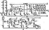
tube. The most prominent parts of the schematic is the voltage multiplier to the right and the voltage divider
for the detector to the left. Below this, is the GM tube.
The circuit board
is in the middle of the box. The blue electrolytic capacitors at the bottom are part of the voltage doubler, giving
800-900 volts to the GM tube. The tube itself is lying down to the right, with its hat off. The round, black thing
is the thin detector window. This window is so thin, both beta and alpha particles can penetrate it and ionise
the gas inside the tube. Gamma radiation, on the other hand, is detected by the electrons it knocks out of the
nickel walls of the tube, which in their turn builds an ionised bridge in the detector gas, and so trigger the
tube. The most prominent parts of the schematic is the voltage multiplier to the right and the voltage divider
for the detector to the left. Below this, is the GM tube.
I got some uranium nitrate (UO2 (NO3)2+6H2O) from a friend and was finally able to verify that
the counter worked, that the intensity of the radiation decreased with the square of the distance, that paper would
attenuate this and that much, but that was all. Later, I realised that the levels of radiation in nature were much
lower, and needed instruments of a more advanced kind.
Prototyping Breadboards
Building electronic prototypes, especially in the high-frequency domain, can be really problematic if you haven't
got some good prototype board to build on. Wire-wrapping doesn't work very well for audio and high frequencies,
and universal breadboards with a 2.54" hole matrix and straight copper strips on the underside (à la
Veroboard) are difficult to solder (and re-solder) and are not very useful for high frequencies, as they lack a
ground plane. It's difficult mounting shielding, too.
 I manufactured my own universal breadboard,
which solved the problem. It had a building matrix for IC's with 2.54" spacing on the top side, plus areas
for analogue circuitry and lines for low impedance power feed. The underside was completely covered with tinned
copper laminate, making for safe and good shielding and low impedance earthing. You can't have much lower impedance
to ground than just drilling a hole straight through the board and soldering the component to the ground plane.
I manufactured my own universal breadboard,
which solved the problem. It had a building matrix for IC's with 2.54" spacing on the top side, plus areas
for analogue circuitry and lines for low impedance power feed. The underside was completely covered with tinned
copper laminate, making for safe and good shielding and low impedance earthing. You can't have much lower impedance
to ground than just drilling a hole straight through the board and soldering the component to the ground plane.
Constructions on this type of board had characteristics close to those attainable with customized, factory made
circuit boards.

 This lethal thing should make any electricity safety
inspector gasp for his breath. It is just a simple 300 VDC power supply I built for development work with electron
tubes. It's a simple design. A rectifier salvaged from a TV set (the red one with fins) is mounted on a black acrylic
plate, together with a coil from a fluorescent tube assembly and two electrolytic capacitors from the same TV set
(the upright standing metal cans). A fuse is mounted in one corner. It's 220 VAC straight in. The device has no
feet, and had to be put on something insulating, or I would get very nasty sparks from the underside. Terrible.
But if you just keep your hands off, there is no danger. I can't remember ever getting any shocks from any of my
designs.
This lethal thing should make any electricity safety
inspector gasp for his breath. It is just a simple 300 VDC power supply I built for development work with electron
tubes. It's a simple design. A rectifier salvaged from a TV set (the red one with fins) is mounted on a black acrylic
plate, together with a coil from a fluorescent tube assembly and two electrolytic capacitors from the same TV set
(the upright standing metal cans). A fuse is mounted in one corner. It's 220 VAC straight in. The device has no
feet, and had to be put on something insulating, or I would get very nasty sparks from the underside. Terrible.
But if you just keep your hands off, there is no danger. I can't remember ever getting any shocks from any of my
designs.