D/A Converter Testing
The reason I started with computers somewhere around the beginning of the 80's was not that I was curious about the technology. There was no one around to explain how a microcomputer worked and the books at the municipal library were all at least 15 years too old. Instead, I had become fascinated by space and wanted to build a spaceship simulator. I imagined that computers would probably be good for drawing stars on a TV screen, and for manoeuvring the chair I would be sitting in, to simulate the G-forces. I had sketches of the mechanics, but I had absolutely no idea of how to pull the project through, or the amount of time it would take. In those days I was more interested in motors and radio, and had just started reading Science Fiction.
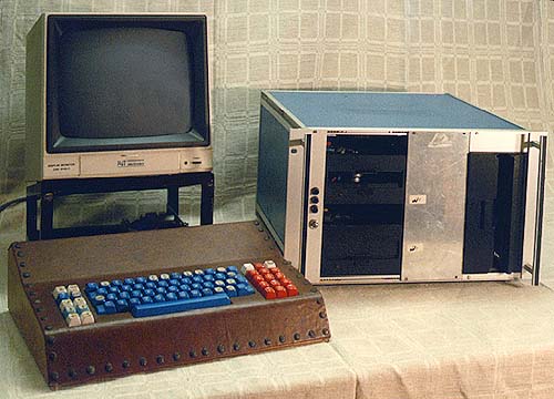 Here you see a family portrait of my
very first home-brew computer. The processor was a CP/M compatible design with an 8085A CPU taken from a blood
analysing machine, made by Clinicon, a Swedish manufacturer of medical electronics (not shown). I used this machine
for systems development and word processing with WordStar for several years. To me, WordStar 0.91 still stands
as a not too bad word processing program. It had all you needed: input, cut and paste, printing and saving. What
more do you really need?
Here you see a family portrait of my
very first home-brew computer. The processor was a CP/M compatible design with an 8085A CPU taken from a blood
analysing machine, made by Clinicon, a Swedish manufacturer of medical electronics (not shown). I used this machine
for systems development and word processing with WordStar for several years. To me, WordStar 0.91 still stands
as a not too bad word processing program. It had all you needed: input, cut and paste, printing and saving. What
more do you really need?
 The leather-clad keyboard is my pride. The
keyboard electronics is made up of hall element switches from Keytronics, mounted on a circuit board. To be able
to manage multimedia applications (of which there were none, around 1980) I provided the keyboard with two joysticks
(removed in the picture). The sides are made of high-grade wood and the edges are nailed with brass furniture nails.
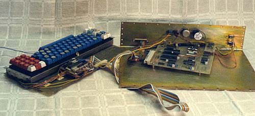
The leather top gives a feeling of England and Chesterfield somehow. Luxury computing, in other words. The next
picture shows the keyboard disassembled. At the far back of the keyboard electronics, my home-brew parallel-to-serial
converter sits, changing the keyboard codes into 8-bit serial ASCII, favoured by the computer. In the middle of
the metal sheet is the monitor driver board (the proper term today would be graphics board), that got its serial
data from the computer and created video for the television screen I used for monitor.
The leather-clad keyboard is my pride. The
keyboard electronics is made up of hall element switches from Keytronics, mounted on a circuit board. To be able
to manage multimedia applications (of which there were none, around 1980) I provided the keyboard with two joysticks
(removed in the picture). The sides are made of high-grade wood and the edges are nailed with brass furniture nails.
The leather top gives a feeling of England and Chesterfield somehow. Luxury computing, in other words. The next
picture shows the keyboard disassembled. At the far back of the keyboard electronics, my home-brew parallel-to-serial
converter sits, changing the keyboard codes into 8-bit serial ASCII, favoured by the computer. In the middle of
the metal sheet is the monitor driver board (the proper term today would be graphics board), that got its serial
data from the computer and created video for the television screen I used for monitor.
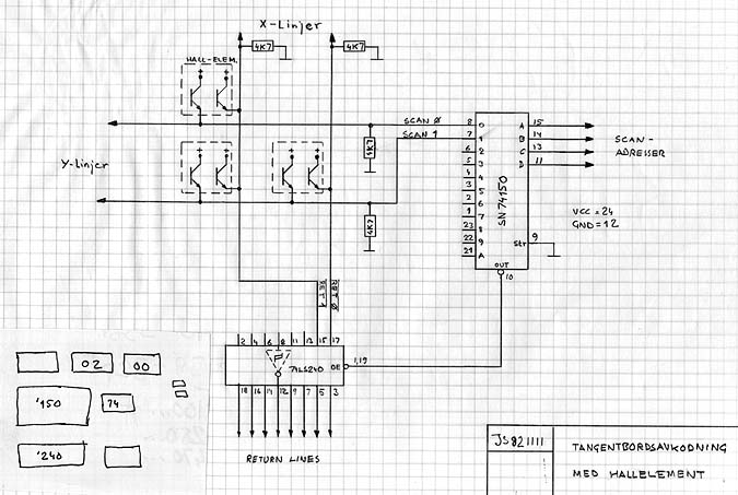 These schematics show
various versions of the keyboard decoder and parallel-to-serial converter, the one that is mounted to the keyboard
electronics, above.
These schematics show
various versions of the keyboard decoder and parallel-to-serial converter, the one that is mounted to the keyboard
electronics, above.
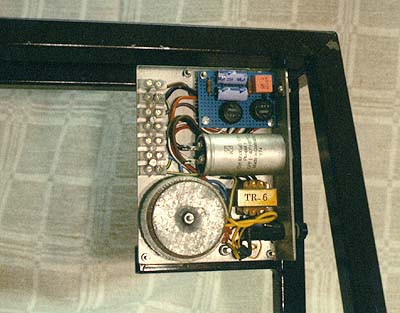 Elegantly mounted in the monitor stand,
is the power supply for the keyboard. The stand was gas welded by my poor father. It's very nicely made, of 15x15
mm square iron tubing. The supply is a very ordinary linear regulated supply, with a big transformer for 5 volts
and one minimal transformer for 12 volts, as there were only a few mA needed for the RS-232 drivers.
Elegantly mounted in the monitor stand,
is the power supply for the keyboard. The stand was gas welded by my poor father. It's very nicely made, of 15x15
mm square iron tubing. The supply is a very ordinary linear regulated supply, with a big transformer for 5 volts
and one minimal transformer for 12 volts, as there were only a few mA needed for the RS-232 drivers.
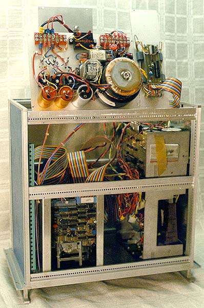 Finally, the insides of the disk drive box. This
magnificent work is a large size 19" rack drawer, containing two full height eight inch and two five inch
diskette drives, large as big-ish shoe boxes. Standing on the top is the power supply, and the optic relay for
switching 220 VAC to the diskette drives. The 8-inch units had asynchronous motors driven directly from the power
line. I had implemented a time delay, shutting off the motors if the drives hadn't been accessed for some time.
This decreased wear on the diskettes and on the little pressure pad pushing the diskette against the read head.
In those days, the diskettes were single-sided. To the right of the power supply sits the part of the interface
taking care of the time delay.
Finally, the insides of the disk drive box. This
magnificent work is a large size 19" rack drawer, containing two full height eight inch and two five inch
diskette drives, large as big-ish shoe boxes. Standing on the top is the power supply, and the optic relay for
switching 220 VAC to the diskette drives. The 8-inch units had asynchronous motors driven directly from the power
line. I had implemented a time delay, shutting off the motors if the drives hadn't been accessed for some time.
This decreased wear on the diskettes and on the little pressure pad pushing the diskette against the read head.
In those days, the diskettes were single-sided. To the right of the power supply sits the part of the interface
taking care of the time delay.
The outcome of all my thoughts around computing hardware was this 19 inch marvel, the Ooga-Booga-box, a 16-bit minicomputer with an Intel 8086 processor. It had an impressive 64 kB of RAM, but no luxuries such as diskette drives or a hard disk. At the time I had an ASR 33 teletype, which could punch and read paper tape, so the data storage problem was no problem, as I saw it then.
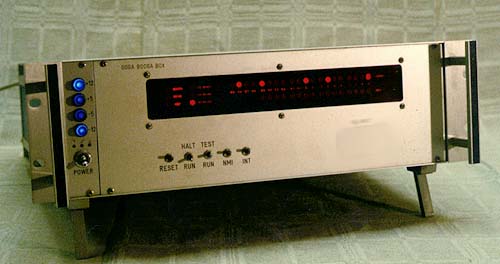 The front panel was built to impress. From
the left we see the power switch and indicator lamps for all voltages. The black display with the red LED's shows
the status for the address and data buses, plus interrupts and other signals of the system. Below this is a set
of switches for interrupt, reset, single-stepping etc.
The front panel was built to impress. From
the left we see the power switch and indicator lamps for all voltages. The black display with the red LED's shows
the status for the address and data buses, plus interrupts and other signals of the system. Below this is a set
of switches for interrupt, reset, single-stepping etc.
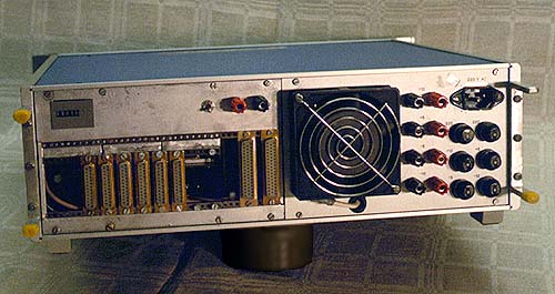 The rear panels is a work of art. At
the bottom left there are connectors for various input and output signals. Note that they are mounted on modularised
panel-ettes made for expansion. I could select how many 25-pin or 50-pin connectors to use at any instant. At the
upper left is the runtime meter. Following to the right is the cooling fan and to the right of this, there are
banana sockets from which all supply voltages could be taken, and used for external equipment, interfaces, measuring
devices etc. To the extreme right are the fuse holders and the power intake.
The rear panels is a work of art. At
the bottom left there are connectors for various input and output signals. Note that they are mounted on modularised
panel-ettes made for expansion. I could select how many 25-pin or 50-pin connectors to use at any instant. At the
upper left is the runtime meter. Following to the right is the cooling fan and to the right of this, there are
banana sockets from which all supply voltages could be taken, and used for external equipment, interfaces, measuring
devices etc. To the extreme right are the fuse holders and the power intake.
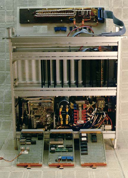
 This is the
unit disassembled. At the front you see three circuit boards, from the left, the serial I/O board, the CPU board
(the 8086 is the discretely grey ceramic chip wit a black top) and lastly the PROM board containing the monitor
software. Behind them the rack box itself, at the bottom of which you see the power supplies, consisting of, from
the right, the soft start relay, a big transformer, two biggish smoothing capacitors and to the far left, stacked
on top of each other, several Boschert low voltage switched power supplies. In other words, a hybrid design somewhere
between linear and switched.
This is the
unit disassembled. At the front you see three circuit boards, from the left, the serial I/O board, the CPU board
(the 8086 is the discretely grey ceramic chip wit a black top) and lastly the PROM board containing the monitor
software. Behind them the rack box itself, at the bottom of which you see the power supplies, consisting of, from
the right, the soft start relay, a big transformer, two biggish smoothing capacitors and to the far left, stacked
on top of each other, several Boschert low voltage switched power supplies. In other words, a hybrid design somewhere
between linear and switched.
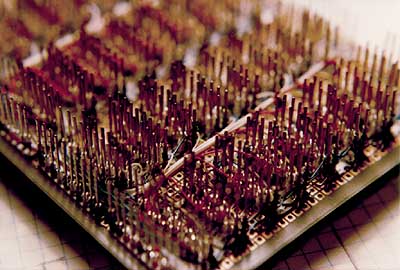
I invented the 96-pin data bus myself, and wire-wrapped the back plane (over 1000 wrapping operations, huff puff). On top of everything is the front panel with its impressive display stuck full of LED's. The other picture is a close-up the memory board, housing as much as 64 kB. The memory is assembled out of 32 type 4116 1 bit x 4k dynamic memory chips. The refresh is handled by a special chip dubbed the 8202. Nice! Lovely! Working!
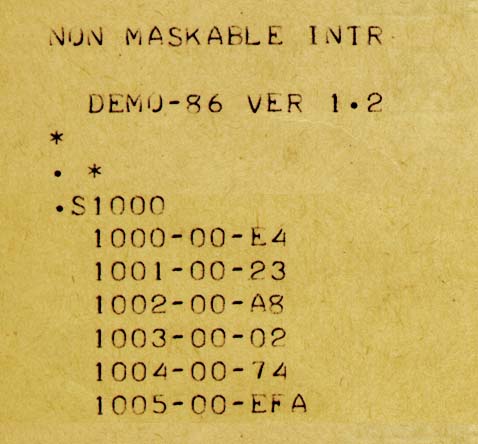 Imagine how proud I was when the monitor programme identified itself for
the first time. Its name was DEMO-86. To me, seeing this printout is an incredible nostalgia trip.
Imagine how proud I was when the monitor programme identified itself for
the first time. Its name was DEMO-86. To me, seeing this printout is an incredible nostalgia trip.
 The first picture shows the CPU board schematics. The colours indicate the colours of
the wire wrap wires used to identify the various signals. The next picture shows how the wiring was done in practice.
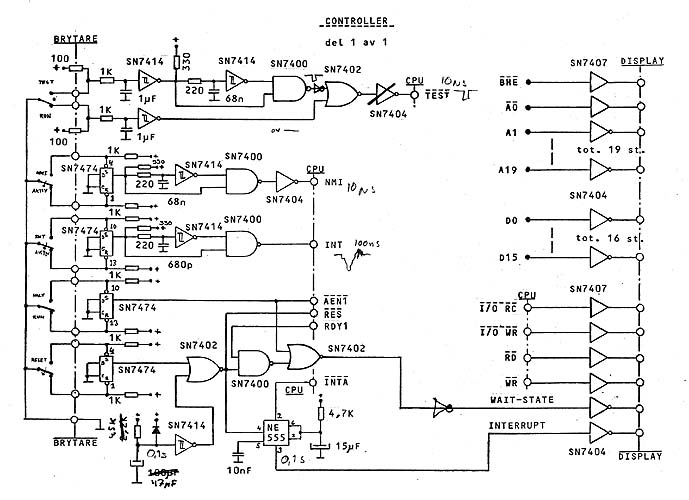
The third picture shows the schematics of the Controller board, i.e. the board used for controlling the events
in the machine, such as reset, interrupts etc., and also what was to be displayed on the display.
The first picture shows the CPU board schematics. The colours indicate the colours of
the wire wrap wires used to identify the various signals. The next picture shows how the wiring was done in practice.
The third picture shows the schematics of the Controller board, i.e. the board used for controlling the events
in the machine, such as reset, interrupts etc., and also what was to be displayed on the display.
 The power supply was built very methodically,
to give the least possible problems later, at maintenance time. As you can see from the schematics, all wires have
a number, which was taped onto them during construction. The numbers were chosen out of different number series
for different functions: earthing, live voltage, soft start etc.
The power supply was built very methodically,
to give the least possible problems later, at maintenance time. As you can see from the schematics, all wires have
a number, which was taped onto them during construction. The numbers were chosen out of different number series
for different functions: earthing, live voltage, soft start etc.
After that, the IBM PC arrived to spoil all the fun.
I lived in Södertälje and needed to get in touch with the computers at the Royal Institute of Technology in Stockholm. As payment for a service trip to Norway, I got a CRT terminal, which would today be termed a Dumb Terminal, a 7-bit ASCII terminal. But I needed a modem. In those days 300 bps was the standard, something well within the reach of a hobbyist.
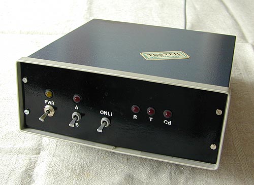
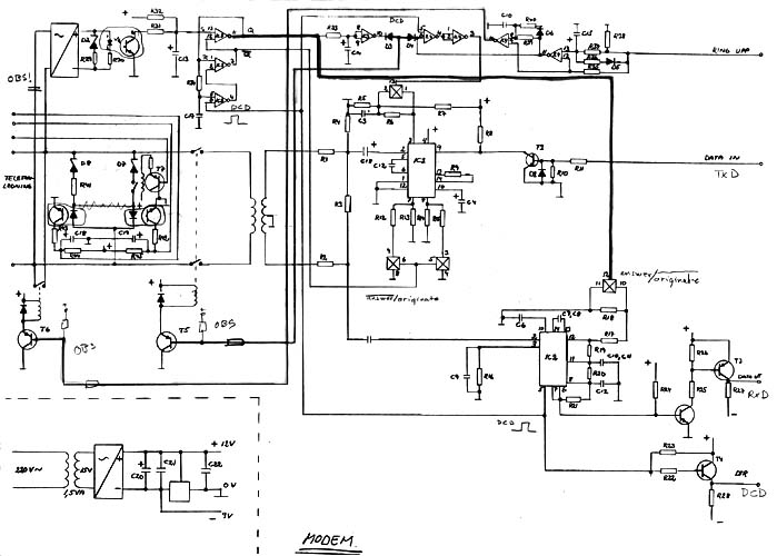 Modems were sold
only by the Telecommunications Authority Monopoly, but far too expensive for a hobbyist. I had to build it myself.
I made circuit boards, and I built three modems, just to have some spares if one would break. Of course, the two
extra ones were quickly borrowed by friends, but mine never broke so it didn't matter.
Modems were sold
only by the Telecommunications Authority Monopoly, but far too expensive for a hobbyist. I had to build it myself.
I made circuit boards, and I built three modems, just to have some spares if one would break. Of course, the two
extra ones were quickly borrowed by friends, but mine never broke so it didn't matter.
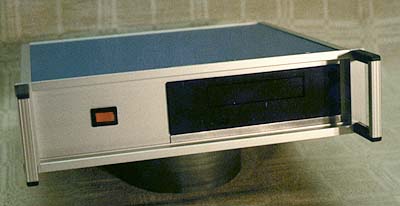 A complete failure. Not so
much the construction, as the main component. There was beginning to appear little data cassettes called QIC-40
on the market, which would store 40 megabytes. That was a lot in those days. This type of tape station was connected
to the floppy drive interface, which, I would find out, was not very lucky when it came to error checking. Because
I believed I would get more than one computer, I bought an internal QIC-40 station and built it into a very nice
box with power supply and equipped it with a cable, enabling it to be moved between the machines. Portable tape
stations were barely thought of in 1989.
A complete failure. Not so
much the construction, as the main component. There was beginning to appear little data cassettes called QIC-40
on the market, which would store 40 megabytes. That was a lot in those days. This type of tape station was connected
to the floppy drive interface, which, I would find out, was not very lucky when it came to error checking. Because
I believed I would get more than one computer, I bought an internal QIC-40 station and built it into a very nice
box with power supply and equipped it with a cable, enabling it to be moved between the machines. Portable tape
stations were barely thought of in 1989.
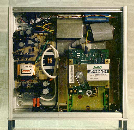 The tape station itself sits at the bottom
left, and to the right is a switched power supply. The tape station became so very hot I had to put in a cooling
fan. It is located behind the bent metal sheet at the middle top. Unfortunately, it would turn out that the tape
station itself was a complete failure, the driver software was bad, and the Swedish reseller got into a fight with
the manufacturer. Everything worked so badly, I could never use the tape station. If we had had the Internet, I
may have been able to get new driver from there, but in those days I had nowhere to go. Nowadays 40 megabytes are
nothing, so there is no use even thinking of trying to revive it again.
The tape station itself sits at the bottom
left, and to the right is a switched power supply. The tape station became so very hot I had to put in a cooling
fan. It is located behind the bent metal sheet at the middle top. Unfortunately, it would turn out that the tape
station itself was a complete failure, the driver software was bad, and the Swedish reseller got into a fight with
the manufacturer. Everything worked so badly, I could never use the tape station. If we had had the Internet, I
may have been able to get new driver from there, but in those days I had nowhere to go. Nowadays 40 megabytes are
nothing, so there is no use even thinking of trying to revive it again.
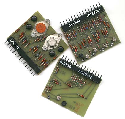 I had very bold plans to get myself some really big
hard disks, cheaply. Table-top hard disks cost immeasurable sums in those days. I bought three 10 megabyte hard
disk drives cheaply from Control Data Corporation. They were antique. I put them in the garage because they were
the same size as dishwasher machines. They had removable 5-floor disk packs that were mounted from the top, and
they rumbled like wild animals. After having realised the difficulties of interfacing them to my home computer,
they were removed from my collection. I only kept a few circuit boards as souvenirs. The boards in the picture
contain some simple logic functions built with discrete components, a few OR-gates, a driver stage or something,
what is today miniaturized to a few square micrometers in one corner of a silicon chip. There were several hundreds
of these inside the disk drive box.
I had very bold plans to get myself some really big
hard disks, cheaply. Table-top hard disks cost immeasurable sums in those days. I bought three 10 megabyte hard
disk drives cheaply from Control Data Corporation. They were antique. I put them in the garage because they were
the same size as dishwasher machines. They had removable 5-floor disk packs that were mounted from the top, and
they rumbled like wild animals. After having realised the difficulties of interfacing them to my home computer,
they were removed from my collection. I only kept a few circuit boards as souvenirs. The boards in the picture
contain some simple logic functions built with discrete components, a few OR-gates, a driver stage or something,
what is today miniaturized to a few square micrometers in one corner of a silicon chip. There were several hundreds
of these inside the disk drive box.