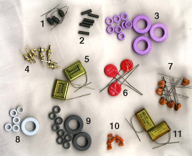
The picture shows a number of components used for various interference situations, for blocking different types of interference in different frequency ranges, and with different mounting methods.
|
1 |
Wirewound coil |
2 |
Ferrite tube |
3 |
Ferrite ring |
|
4 |
Feed-through capacitor |
5 |
Plastic foil capacitor |
6 |
Varistor |
|
7 |
Capacitor-ferrite combination |
8 |
Ferrite ring |
9 |
Ferrite ring |
|
10 |
Ferrite tube |
11 |
RC-link |
|
|
These components have a value of only a few pence each, but still many appliance manufacturers exclude them to save a little money. Often, interference elimination is more about logic and planning than about the components themselves.
Description |
1. Wirewound coils have large inductance and are used for attenuating interference of low frequencies, in the kilohertz area. An example of this could be interference from small motors.
2. Ferrite tubes attenuate at higher frequencies and are advantageously used in audio and computer equipment, where they are threaded directly on the emitting wire. Ferrite is non-conductive, so the rings can be put on bare wires. They are small and may be mounted on wires inside connectors. Everything seems to be squirting 100 MHz and above, these days. Every little home computer has a Pentium with a clock circuit generating at least 133 MHz square wave.
 |
3. Ferrite rings, toroids are intended to be wound with insulated wire, and are used at higher interference levels, for example from larger motors or other inductances. Either you wind it with one wire and get an inductor, or you wind with two in parallel and get a bifiliar coil, in which the interference currents cancel out. For suppression in larger switched power supplies, there are large, molded ferrite rings that may be soldered directly on the circuit board. The picture shows permeability curves for some common ferrite types, meaning, in short, how good they are at absorbing magnetic fields at various frequencies. |
 |
5. Capacitors may be used alone or in combination with other components to suppress interference, for example in fluorescent tube assemblies or switches. Metallized mylar foil has the nice advantage that the capacitor is self healing after a overvoltage transient has shot a hole through it. The picture shows some schematics with typical uses of suppressing capacitors. |
 |
6. Varistors, or metal oxide varistors (MOV) are components that clamp voltage transients between two conductors by short-circuiting them. Varistors are used in heavy applications, such as motors and relays, or for lightning protection. The varistor is slowly worn out and will become more and more short-circuited during its lifetime. It reacts in a few microseconds, and larger models may absorb several thousands of joules of electric energy. The picture shows curves of breakdown voltages for some common varistors, that is, at what voltage the varistor goes short-circuit. |
 |
Zener diodes have the same area of use as varistors. They are often put in digital circuits to protect from backward polarization, overvoltages from broken power supplies etc. The zener diode reacts in a few picoseconds and should preferably melt down before the rest of the equipment. That calls for short component leads. Otherwise, the leads will create high impedances and completely spoil the diode. The picture shows a voltage fluctuation, an unclamped transient at the top, and the same transient being clamped by a varistor at the bottom. The fluctuation spans no more than a few microseconds. |
 |
7. Capacitor-ferrite combinations are the nicest and most convenient components available for interference suppression on circuit boards. They are used in filter banks, they are small, have a well defined attenuation curve and may be flow soldered. The picture shows the attenuation curve in decibels for a circuit board filter, for frequencies up to 1 GHz. |
 |
Other components for interference suppression are various types of screening braids, bronze spring finger stock, or conductive tape, rubber and plastic, that may not look so exciting in a picture. Maybe the most common suppression component today is the line filter. It is a combination of a mains receptacle and a filter, and it sits at the back of every personal computer. The picture illustrates its schematic and gives some typical attenuation figures in decibels. There are symmetric and asymmetric attenuation: attenuation between the mains leads and earth, and attenuation of interference between one mains lead and ground. |
Methods |
The most common problem is interference being radiated from one cable to another. The simplest solution then is to move the cables apart, or to shield them. Interference radiation decreases by the square of the distance.
More expensive components generally make less noise than cheaper ones. In the long run it may be better to use a more expensive motor, creating less noise, than a cheaper one, causing problems with various PTT's later, plus having to spend many hours of troubleshooting.
Non-Methods |
Sometimes interference suppression components are incorrectly used, or are mounted in such a way that their effect is cancelled by other phenomena in the apparatus or the environment. If the enclosure is made of plastic, radiated interference from nearby cables or from static discharges may completely eliminate the effect of the suppressive component mounted on the apparatus' own leads.
Very few suppression components will protect against lightning. Lightning protective mains junction boxes, power bars, are just another way for someone to make money on nothing. Lightning is mainly a radiated phenomenon, from which no little box in the world will protect.
To protect from lightning damage you need a low impedance earth. There is no such thing in an ordinary flat. The power company's earth is very good for grounding mains voltage, but not for the microwaves of the lightning.